Matrix Keypad Interfacing — A Build Roadmap
A standalone assignment that pulls together Experiment 5 (GPIO polling) and Experiment 6 (SysTick and GPTM timers) into one build: a 4x4 matrix keypad, scanned continuously in the background, driving the onboard RGB LED.
Target device: TM4C123GH6PM.
Introduction
What Is a Matrix Keypad?
A 4x4 keypad packs 16 keys into just 8 pins — 4 rows and 4 columns. Each key sits at exactly one row/column crossing, and pressing it is the only thing that ever joins that row to that column.
Since there's no way to read 16 independent switches through 8 wires all at once, you scan instead: drive one row HIGH at a time while the rest stay LOW, and read the columns, which are pulled down so they idle LOW. If a column reads HIGH while row N happens to be the active one, the key at (row N, that column) is being pressed. Cycle through all four rows quickly enough and the whole thing feels instant.
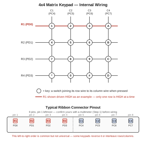
The bottom half of the diagram shows the physical 8-pin ribbon connector most of these keypads ship with, left-to-right R1–R4 then C1–C4. Treat that order as a starting guess, not a fact: cheap keypads aren't always labeled or wired consistently, so confirm yours with a multimeter before wiring anything up (this is exactly what Step 1's verification below checks).
Hardware Setup
| Signal | Pin | Direction |
|---|---|---|
| ROW1–ROW4 | PD0–PD3 | Output |
| COL1–COL4 | PC4–PC7 | Input, pull-down |
| RGB LED (onboard) | PF1 / PF2 / PF3 | Output (Red / Blue / Green) |
Rows idle LOW and are driven HIGH one at a time; columns rely on the internal pull-downs (PDR). The onboard RGB LED needs no special handling here — use it exactly as in earlier experiments.
Key Actions
Whichever step you're on, every accepted press routes through KeyPad_HandleKey. Here's the full target behavior:
| Key(s) | Action |
|---|---|
1 2 3 | Red / Green / Blue |
4 5 6 | Red+Green / Red+Blue / Green+Blue |
7 | Red+Green+Blue (white) |
0 | All off |
A | Start/pause blink |
B / C | Increase / decrease speed |
D | Reset interval to 2 s |
The color keys (Step 3) just set which LED bits are on. Keys A–D (Step 5) drive a second, independent timer — Timer1A, in 32-bit mode — that blinks whichever color is currently active. It starts at a 2-second interval, and B/C nudge that interval up or down by 0.25 s with every press — down to a floor of 0.25 s (fastest), up to a ceiling of 10 s (slowest).
Floor and ceiling
B and C must never push the interval past BLINK_MIN or BLINK_MAX — go faster than 0.25 s and it stops looking like a blink; go slower than 10 s and it stops looking like blinking at all. Enforce both before you touch TAILR, not after: on an unsigned value, subtracting past the floor doesn't give you a negative number, it wraps around to something enormous. So check if (reload >= BLINK_MIN + BLINK_STEP) before subtracting, and if (reload + BLINK_STEP <= BLINK_MAX) before adding — never subtract or add first and check the result.
Build Steps
You get two files to fill in — keypad.c/keypad.h hold all the keypad and LED logic, main.c just calls into them. Every function is stubbed out with // TODO comments and builds cleanly as-is; no logic is implemented yet.
#include "TM4C123.h"
#include "keypad.h"

int main(void)
{
    KeyPad_GPIO_Init();
    SysTick_Config(SystemCoreClock / 1000);   // ~1 ms tick, drives the row scan
    Blink_Timer_Init();

    while (1) {
        KeyPad_Poll();
    }
}#include "keypad.h"
const char keymap[4][4] = {0}; // TODO: fill in row-major, matching your wiring diagram
volatile uint32_t global_ms = 0;
volatile uint8_t current_row = 0;
void KeyPad_GPIO_Init(void)
{
// TODO -- Step 1: enable the clocks for GPIOC, GPIOD, GPIOF (RCGCGPIO)
// TODO -- Step 1: PD0-3 as outputs -- DIR, DEN -- idle LOW
// TODO -- Step 1: PC4-7 as inputs -- DEN, PDR (pull-down)
// TODO -- Step 1: PF1-3 as outputs -- DIR, DEN
}
void SysTick_Handler(void)
{
// TODO -- Step 2: increment global_ms
// TODO -- Step 2: drive current_row HIGH and every other row LOW, then advance
// current_row to the next value (0-3, wrapping back to 0)
}
void KeyPad_Poll(void)
{
// TODO -- Step 2: read COL_MASK while current_row is whatever SysTick left active
// TODO -- Step 2: if exactly one column reads HIGH, decode (current_row, column)
// through keymap and call KeyPad_HandleKey
// TODO -- Step 6: decode using the row that was active when you actually
// read the columns, not a re-read of current_row later
// TODO -- Step 6: debounce with DEBOUNCE_MS, and don't re-fire while the
// same key is still held down
}
void Blink_Timer_Init(void)
{
// TODO -- Step 4: enable the Timer1 clock (RCGCTIMER)
// TODO -- Step 4: CFG = 0x0 (32-bit mode), TAMR = periodic mode
// TODO -- Step 4: TAILR = BLINK_DEFAULT - 1
// TODO -- Step 4: clear + enable the timeout interrupt, enable NVIC IRQ for TIMER1A
// TODO -- Step 4: leave the timer itself disabled (CTL) -- 'A' starts it, in Step 5
}
void TIMER1A_Handler(void)
{
// TODO -- Step 4: clear the timeout interrupt (ICR)
// TODO -- Step 4: toggle the active color on/off on the RGB LED
}
void KeyPad_HandleKey(char key)
{
switch (key) {
// TODO -- Step 3: cases '1'-'7' set the LED color combination, '0' clears it
// (see the Key Actions table)
// TODO -- Step 5: case 'A' toggles blink on/off (enable/disable Timer1A via CTL)
// TODO -- Step 5: case 'B' decreases the blink interval by BLINK_STEP,
// floored at BLINK_MIN -- check before you subtract
// TODO -- Step 5: case 'C' increases the blink interval by BLINK_STEP,
// capped at BLINK_MAX -- check before you add
// TODO -- Step 5: case 'D' resets the interval to BLINK_DEFAULT
default:
break; // 8, 9, *, # -- left unused
}
}#ifndef KEYPAD_H
#define KEYPAD_H
#include "TM4C123.h"
// ---- Rows: PD0-PD3 (outputs) ----
#define ROW_MASK 0x0F // PD0-PD3
// ---- Columns: PC4-PC7 (inputs, pull-down) ----
#define COL1 0x10 // PC4
#define COL2 0x20 // PC5
#define COL3 0x40 // PC6
#define COL4 0x80 // PC7
#define COL_MASK (COL1 | COL2 | COL3 | COL4)
// ---- Onboard RGB LED: Port F ----
#define RED_LED 0x02 // PF1
#define BLUE_LED 0x04 // PF2
#define GREEN_LED 0x08 // PF3
#define LED_MASK (RED_LED | BLUE_LED | GREEN_LED)
// ---- Blink timer: Timer1A, 32-bit mode ----
#define TICKS_PER_SEC 50000000UL // 50 MHz system clock
#define BLINK_DEFAULT (2 * TICKS_PER_SEC) // 2 s
#define BLINK_STEP (TICKS_PER_SEC / 4) // 0.25 s
#define BLINK_MIN (TICKS_PER_SEC / 4) // 0.25 s floor -- fastest allowed
#define BLINK_MAX (10 * TICKS_PER_SEC)// 10 s ceiling -- slowest allowed
#define DEBOUNCE_MS 25 // Step 6 -- minimum time between accepted presses
extern const char keymap[4][4]; // TODO: fill in -- matches the wiring diagram
extern volatile uint32_t global_ms; // free-running millisecond counter
extern volatile uint8_t current_row; // row currently driven HIGH (0-3)
void KeyPad_GPIO_Init(void); // Step 1
void SysTick_Handler(void); // Step 2
void KeyPad_Poll(void); // Step 2 & 6 -- call every main-loop iteration
void Blink_Timer_Init(void); // Step 4
void TIMER1A_Handler(void); // Step 4
void KeyPad_HandleKey(char key); // Steps 3 & 5 -- action for `key`, see assignment table
#endif // KEYPAD_HFill it in through the six steps below, in order. Each one ends with a way to check your work in the Keil debugger before moving to the next — don't start Step N+1 until Step N's check actually passes.
Step 1: Configure the Ports
Fill in KeyPad_GPIO_Init: clocks for GPIOC/GPIOD/GPIOF, then DIR/DEN for the rows (outputs, idle LOW), DEN/PDR for the columns (inputs, pull-down), and DIR/DEN for the RGB LED (outputs).
void KeyPad_GPIO_Init(void)
{
    // TODO: enable the clocks for GPIOC, GPIOD, GPIOF
    // TODO: PD0-3 as outputs -- DIR, DEN -- idle LOW
    // TODO: PC4-7 as inputs -- DEN, PDR (pull-down)
    // TODO: PF1-3 as outputs -- DIR, DEN
}
Verify on the board/debugger:
- Breakpoint right after
KeyPad_GPIO_Init()returns. WatchGPIOD->DIR/DEN(bits 0–3 set),GPIOC->DEN/PDR(bits 4–7 set) andGPIOC->DIR(bits 4–7 clear),GPIOF->DIR/DEN(bits 1–3 set). - With execution still paused, hand-edit
GPIOD->DATAin the Watch window and confirm with a multimeter that the matching physical row pin actually goes HIGH — a wiring mistake here looks identical to a software bug in every step after this one.
Step 2: Scan Rows, Poll Columns, Verify Every Key
Fill in SysTick_Handler (advance the row scan) and KeyPad_Poll (read the columns and decode a press).
void SysTick_Handler(void)
{
    // TODO: increment global_ms
    // TODO: drive current_row HIGH and every other row LOW,
    //       then advance current_row to the next value (0-3, wrapping)
}

void KeyPad_Poll(void)
{
    // TODO: read COL_MASK while current_row is whatever the scan left active
    // TODO: if exactly one column is HIGH, decode (current_row, column)
    //       through keymap and call KeyPad_HandleKey
}
Verify in three passes, in order:
- Scan alone — watch
current_rowcycle 0→1→2→3→0… roughly once per millisecond (or watchGPIOD->DATA & ROW_MASK). - Raw wiring, before
keymap— leavekeymapblank, breakpoint where you'd decode the column, and press each of the 16 keys physically. Record the(row, column)pair each one produces and compare it against the diagram — akeymapfilled in against a guess instead of a measurement makes every later step look broken even when it isn't. - Decoded key — once your table matches the diagram, fill in
keymapand letKeyPad_PollcallKeyPad_HandleKey. Breakpoint inside it and confirm thekeyparameter is correct for all 16 keys (nothing visible happens yet —KeyPad_HandleKeyis still empty).
Step 3: Control the LEDs (Keys 0–7)
Fill in the '0'–'7' cases in KeyPad_HandleKey, per the Key Actions table above.
void KeyPad_HandleKey(char key)
{
    switch (key) {
        // TODO: cases '1'-'7' set the LED color combination, '0' clears it
        ...
    }
}
Verify: press 1–7, confirm the right color combination lights up; press 0, confirm all off. Then check GPIOF->DATA in the Watch window bit-by-bit against LED_MASK for a couple of keys — two wrong bits can still produce a plausible-looking color by coincidence.
Step 4: Bring Up the Blink Timer
Fill in Blink_Timer_Init (Timer1A, 32-bit mode, periodic, default reload, interrupt + NVIC enabled, timer itself left disabled) and TIMER1A_Handler (clear the interrupt, toggle the active color).
void Blink_Timer_Init(void)
{
    // TODO: enable the Timer1 clock
    // TODO: CFG = 0x0 (32-bit mode), TAMR = periodic mode
    // TODO: TAILR = BLINK_DEFAULT - 1
    // TODO: enable the timeout interrupt + NVIC IRQ for TIMER1A
    // TODO: leave the timer disabled (CTL) -- 'A' starts it, in Step 5
}

void TIMER1A_Handler(void)
{
    // TODO: clear the timeout interrupt
    // TODO: toggle the active color on/off
}
Verify in isolation, before Step 5 wires in real control: temporarily add TIMER1->CTL |= 0x01; right after Blink_Timer_Init() in main.c, forcing it to run. Confirm the LED blinks at roughly a 2-second rate against a clock, and breakpoint inside TIMER1A_Handler to confirm its hit count climbs by exactly one about every 2 seconds. Delete the forced-enable line once this checks out.
Step 5: Add Enable/Disable Logic
Fill in the 'A'–'D' cases in KeyPad_HandleKey: A toggles Timer1A's enable bit in CTL, B/C adjust TAILR with the floor/ceiling checks from the warning above, D resets TAILR to the default.
switch (key) {
    // TODO: case 'A' toggles blink on/off (enable/disable Timer1A via CTL)
    // TODO: case 'B' decreases the interval by BLINK_STEP, floored at BLINK_MIN
    // TODO: case 'C' increases the interval by BLINK_STEP, capped at BLINK_MAX
    // TODO: case 'D' resets the interval to BLINK_DEFAULT
    ...
}
Verify:
A— LED switches between blinking and holding solid; check it matchesTIMER1->CTL's enable bit at the moment you press it.Bmashed repeatedly —TIMER1->TAILRdecreases byBLINK_STEPeach press and stops exactly atBLINK_MINno matter how many more times you press it. This is the check that matters most: keep pressing well past the floor and confirmTAILRnever wraps to a huge value.C— same check at theBLINK_MAXceiling.D—TAILRresets to the default from any interval you reached withB/C.
Once Step 5 verifies clean, move on to Step 6 — the last piece of the base build.
Step 6: Harden Against Scan Races and Held Keys
Steps 1–5 got you a keypad that reads correctly most of the time — but two real bugs are still lurking, and they show up under exactly the conditions you'd actually use this thing: pressing keys at a normal pace, and holding one down.
The scan race. current_row keeps changing in the background, once every SysTick tick, completely independent of whatever KeyPad_Poll happens to be doing at that moment. If you read the columns, and then separately use current_row again to decode which key that was, what guarantees those two reads saw the same row? What could happen to a key's decoded value if the scan advances in between — and how would you close that gap so a single Poll call always decodes against the row it actually read, no matter what happens after?
No repeat while held. Right now, KeyPad_Poll calls KeyPad_HandleKey on every single call where a key reads as pressed — which, while a key is held, is every few milliseconds, for as long as it's held. Fixing that needs two things: debounce (DEBOUNCE_MS is defined for you — use global_ms to require a minimum time between accepted presses, following the pattern from Experiment 6, Task 1), and a way to recognize "still held" so it isn't treated as a fresh press every time. That second part runs straight into the scan race above: a column reading is only meaningful while its own row is active, so what does it mean if you check "is anything pressed" while the scan happens to be on some other row, and treat "nothing there" as if your held key had been released? What do you need to remember about which row a held key was on, so that revisiting an unrelated row doesn't get mistaken for its release?
void KeyPad_Poll(void)
{
    // TODO -- Step 6: decode using the row that was active when you actually
    //         read the columns, not a re-read of current_row later
    // TODO -- Step 6: debounce with DEBOUNCE_MS, and don't re-fire while the
    //         same key is still held down
}
Verify:
- Scan race — pick two keys that share a column but sit on different rows (any standard phone-style layout has several such pairs). Press one repeatedly at a normal pace and watch closely for the other one's action flashing briefly instead of — or in addition to — the one you actually pressed. It shouldn't happen at all, at any pace.
- Held key — hold a single key down for several seconds and confirm its action fires exactly once, not repeatedly. Then release and immediately press a different key — it should register right away, with no leftover delay from the previous hold.
Once Step 6 verifies clean, the base build is done and fully verified end to end.
Verification Checklist
By this point every item below should already be confirmed from the step-by-step checks above — this is just the final end-to-end pass.
- Wiring — all 16 keys map to the right
(row, column)pair (Step 2). - Colors —
1–7show the right combination, and0clears them (Step 3). - Blink — the default toggles roughly every 2 s;
Astarts and pauses it;B/Cshift the interval by 0.25 s and hold at the floor/ceiling;Dresets it back to 2 s (Steps 4–5). - Reliability — no wrong-row flashes at any pace, and holding a key fires its action exactly once (Step 6).