Universal Asynchronous Receiver-Transmitter (UART)
TM4C123GH6PMComplete Lab Manual
For the complete experiment including learning objectives, theoretical background, and detailed explanations, download the PDF manual: Download Experiment 9 PDF
Examples
#include <stdio.h>
#include "TM4C123.h"
#include "uart.h"

int main(void) {
    UART0_Init();
    UART0_WriteString("Hello World!\r\n");  // Send greeting with newline

    while (1) {
		char buff[MAX_STR_LEN];
		UART0_ReadString(buff, MAX_STR_LEN);

		UART0_WriteString("Received: ");
		UART0_WriteString(buff);
		UART0_WriteString("\r\n");
    }
}#include "uart.h"
void UART0_WriteChar(char c) {
while ((UART0->FR & (1 << 5)) != 0); // Wait until TX FIFO is not full (TXFF bit 5)
UART0->DR = c; // Write character to Data Register
}
void UART0_WriteString(char *str) {
while (*str) { // Loop through each character until null terminator
UART0_WriteChar(*(str++)); // Send each character
}
}
void UART0_Init() {
SYSCTL->RCGCUART |= (1 << 0); // Enable clock to UART0 module
SYSCTL->RCGCGPIO |= (1 << 0); // Enable clock to GPIO Port A
GPIOA->AFSEL |= U0_RX | U0_TX; // Enable alternate function on PA0 (RX) and PA1 (TX)
GPIOA->PCTL |= (1 << 0) | (1 << 4); // Configure PA0 and PA1 for UART (U0RX/U0TX)
GPIOA->DEN |= U0_RX | U0_TX; // Enable digital function for PA0 and PA1
UART0->CTL = 0; // Disable UART0 while configuring
UART0->IBRD = 27; // Set integer baud rate divisor for 115200 baud @ 50MHz
UART0->FBRD = 8; // Set fractional baud rate divisor
UART0->LCRH = 0x60; // 8 data bits, no parity, one stop bit, FIFOs enabled
UART0->CC = 0; // Use system clock for UART
UART0->CTL = (1 << 0) | (1 << 8) | (1 << 9); // Enable UART0, TX and RX
}
char UART0_ReadChar(void) {
while (UART0->FR & (1 << 4)); // Wait while RX FIFO empty (RXFE bit 4)
return (char)(UART0->DR & 0xFF); // Return received character
}
void UART0_ReadString(char *buffer, int maxLen) {
int i = 0;
char c;
while (i < (maxLen - 1)) { // Leave space for null terminator
c = UART0_ReadChar();
if (c == '\r' || c == '\n') { // End of input
break;
}
buffer[i++] = c;
}
buffer[i] = '\0'; // Null terminate the string
}#ifndef UART_H
#define UART_H
#include "TM4C123.h" // Or your MCU's main header
#define U0_TX ( 1 << 1 )
#define U0_RX ( 1 << 0 )
#define MAX_STR_LEN 50
void UART0_WriteChar(char c);
void UART0_WriteString(char *str);
char UART0_ReadChar();
void UART0_ReadString(char *buffer, int maxLen);
void UART0_Init();
#endif // UART_HThe above code demonstrates a simple UART communication setup. The UART0_Init function initializes the UART0 module, while UART0_WriteChar and UART0_ReadChar functions handle data transmission and reception, respectively. To be able to communicate with the microcontroller, you can use a terminal program on your PC PuTTY to send and receive data over the serial port. Make sure to set the baud rate and other parameters to match the configuration in your code. The following image shows how to set up the serial connection in PuTTY:
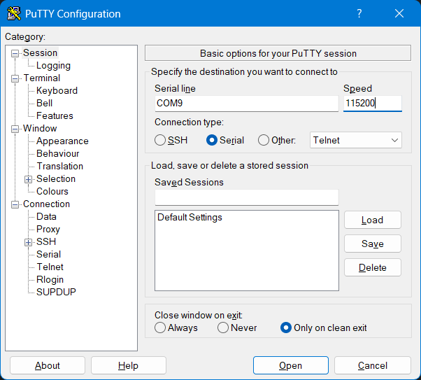
You should replace the COM port with the one assigned to your TM4C123G LaunchPad. You can find this in the Device Manager under Ports (COM & LPT). The baud rate should match the one set in your code (e.g., 115200).