LCD Interfacing and Display Control â
Learning Objectives â
After completing this experiment, you will be able to:
- Understand the architecture and operation of the HD44780-based 16Ã2 LCD module.
- Differentiate between command and data registers and their respective control signals.
- Configure the LCD in 4-bit mode to minimize GPIO pin usage.
- Implement the initialization sequence for 4-bit LCD operation.
- Send commands and data to the LCD using proper timing and enable pulse sequences.
- Display text strings at specific cursor positions on the LCD.
- Implement scrolling and dynamic display effects using LCD commands.
- Integrate LCD interfacing with GPIO and interrupt-driven input from push buttons.
Experiment Overview â
Liquid Crystal Displays (LCDs) are essential output devices in embedded systems, providing a simple and effective way to present information to users. The 16Ã2 character LCD module, based on the HD44780 controller, is one of the most widely used displays in embedded applications. It can display 16 characters per line across 2 lines, making it ideal for status messages, sensor readings, and user interfaces.
Unlike more complex graphical displays, character LCDs are straightforward to interface with microcontrollers, requiring only a few GPIO pins and simple command sequences to achieve full control. The HD44780 controller supports both 8-bit and 4-bit communication modes â the 4-bit mode is particularly popular as it reduces the required number of GPIO pins from 11 to 7 (3 control pins + 4 data pins).
In this experiment, you will:
- Learn the internal architecture of the HD44780 LCD controller and its register structure.
- Understand the difference between 8-bit and 4-bit communication modes.
- Implement the complete 4-bit initialization sequence with proper timing requirements.
- Create a reusable LCD driver library with functions for initialization, command transmission, data display, and cursor control.
- Display static and dynamic text on the LCD.
- Implement scrolling effects and button-controlled display manipulation.
By the end of this lab, you will be able to interface a 16Ã2 LCD module with the TM4C123 microcontroller, implement a complete LCD driver in C, and create interactive display applications combining LCD output with GPIO input and interrupts.
Theoretical Background â
HD44780 LCD Controller Architecture â
The HD44780 is an LCD controller/driver developed by Hitachi and widely adopted as an industry standard for character-based LCD modules. It provides a simple microprocessor interface for controlling alphanumeric displays with minimal external components.
LCD Module Overview â
The 16Ã2 LCD module consists of:
- HD44780 Controller: Manages display operations, character generation, and timing
- LCD Panel: 2 rows à 16 columns of character positions
- Character Generator ROM (CGROM): Contains 208 predefined character patterns (alphanumeric, symbols, Japanese kana)
- Character Generator RAM (CGRAM): 64 bytes for up to 8 user-defined custom characters (5Ã8 pixels each)
- Display Data RAM (DDRAM): 80 bytes storing characters currently displayed (40 bytes per line)
- Backlight: Optional LED backlight for improved visibility
The controller handles all low-level display refresh, character rendering, and cursor management automatically. The microcontroller simply writes characters to DDRAM and issues commands for cursor positioning, display control, and special effects.
LCD Registers â
The HD44780 has two main registers accessible by the microcontroller:
Instruction Register (IR)
The Instruction Register receives commands that control display operations:
- Clear display and return cursor to home
- Set cursor position in DDRAM
- Control display on/off, cursor visibility, and blinking
- Set entry mode (cursor direction, display shift)
- Shift cursor or entire display left/right
- Configure interface width (4-bit or 8-bit), number of lines, and font size
Data Register (DR)
The Data Register receives character codes (ASCII) to be displayed:
- Writing to DR displays a character at the current cursor position
- The cursor automatically advances after each write (direction set by entry mode)
- Reading from DR retrieves the character at the current cursor position (rarely used)
LCD Pin Configuration â
The HD44780 interface consists of 16 pins (some modules have 18 pins with additional backlight control):
| Pin | Name | Description |
|---|---|---|
| 1 | VSS | Ground (0V) |
| 2 | VDD | Power supply (+5V or +3.3V) |
| 3 | V0 | Contrast adjustment (connect to potentiometer) |
| 4 | RS | Register Select: 0 = Instruction (command), 1 = Data (character) |
| 5 | RW | Read/Write: 0 = Write to LCD, 1 = Read from LCD (usually grounded for write-only) |
| 6 | E | Enable: Falling edge latches data/command into LCD |
| 7-14 | D0-D7 | 8-bit data bus (D0-D3 unused in 4-bit mode) |
| 15 | A | Backlight anode (+5V, typically with series resistor) |
| 16 | K | Backlight cathode (Ground) |
4-Bit vs. 8-Bit Communication Mode â
The HD44780 supports two communication modes:
8-Bit Mode â
- Uses all 8 data pins (D0-D7)
- Each command or character requires one write cycle
- Faster communication (single byte transfer)
- Requires 11 GPIO pins total (3 control + 8 data)
4-Bit Mode â
- Uses only upper 4 data pins (D4-D7), D0-D3 are left unconnected
- Each command or character requires two write cycles (upper nibble, then lower nibble)
- Slightly slower due to two transfers per byte
- Requires only 7 GPIO pins total (3 control + 4 data)
- Preferred mode for GPIO-constrained systems
4-Bit Communication Protocol:
- Set RS and RW to appropriate values
- Place upper 4 bits (bits 7-4) on D7-D4
- Generate enable pulse: E high â delay â E low
- Place lower 4 bits (bits 3-0) on D7-D4
- Generate another enable pulse: E high â delay â E low
In this experiment, we use 4-bit mode with the following connections:
- PB0 â RS (Register Select)
- PB2 â E (Enable)
- PB4-PB7 â D4-D7 (Data pins)
- RW â Ground (write-only operation)
LCD Initialization Sequence â
Proper initialization is critical for reliable LCD operation. The HD44780 requires a specific sequence of commands with precise timing delays, especially during the transition to 4-bit mode.
Initialization Steps (4-Bit Mode) â
The initialization sequence must account for the fact that the LCD powers up in 8-bit mode and must be switched to 4-bit mode:
- Wait for power-on stabilization: Delay at least 40 ms after VDD rises to 4.5V
- Initial function set (8-bit interface): Send
0x30(upper nibble only) three times:- First time: Wait > 4.1 ms
- Second time: Wait > 100 Ξs
- Third time: Wait > 100 Ξs
- Switch to 4-bit mode: Send
0x20(upper nibble only), wait > 100 Ξs - Configure display parameters: Now send full 8-bit commands in two nibbles:
0x28: Function set â 4-bit mode, 2 lines, 5Ã8 font0x0C: Display control â Display ON, cursor OFF, blink OFF0x06: Entry mode set â Increment cursor, no display shift0x01: Clear display0x02: Return home
NOTE
Critical Note: Steps 2-3 send only the upper nibble because the LCD is still in 8-bit mode. After step 3 completes, the LCD switches to 4-bit mode, and all subsequent commands must be sent as two nibbles (upper first, then lower).
LCD Command Set â
The HD44780 supports a comprehensive set of commands for display control, cursor manipulation, and special effects.
| Command | Hex Code | Description |
|---|---|---|
| Clear Display | 0x01 | Clears entire display, sets DDRAM address 0, cursor to home |
| Return Home | 0x02 | Sets DDRAM address 0, cursor to home (display content unchanged) |
| Entry Mode Set | 0x04-0x07 | Controls cursor direction and display shift |
0x04 | Cursor moves left, no shift | |
0x06 | Cursor moves right, no shift (default) | |
0x05 | Cursor moves left, display shifts right | |
0x07 | Cursor moves right, display shifts left | |
| Display Control | 0x08-0x0F | Controls display, cursor, and blink on/off |
0x08 | Display OFF | |
0x0C | Display ON, cursor OFF, blink OFF | |
0x0E | Display ON, cursor ON, blink OFF | |
0x0F | Display ON, cursor ON, blink ON | |
| Cursor/Display Shift | 0x10-0x1F | Shifts cursor or display left/right |
0x10 | Shift cursor left | |
0x14 | Shift cursor right | |
0x18 | Shift display left | |
0x1C | Shift display right | |
| Function Set | 0x20-0x3F | Sets interface length, line number, font |
0x28 | 4-bit mode, 2 lines, 5Ã8 font | |
0x38 | 8-bit mode, 2 lines, 5Ã8 font | |
| Set DDRAM Address | 0x80 + addr | Positions cursor at DDRAM address |
0x80 | Beginning of line 1 (address 0x00) | |
0xC0 | Beginning of line 2 (address 0x40) |
DDRAM Address Mapping â
The Display Data RAM (DDRAM) is 80 bytes, but only 32 bytes (16 per line) are visible at any time. Understanding the address mapping is essential for cursor positioning:
| Display Position | DDRAM Address | Command |
|---|---|---|
| Line 1, Column 0 | 0x00 | 0x80 |
| Line 1, Column 1 | 0x01 | 0x81 |
| Line 1, Column 15 | 0x0F | 0x8F |
| Line 2, Column 0 | 0x40 | 0xC0 |
| Line 2, Column 1 | 0x41 | 0xC1 |
| Line 2, Column 15 | 0x4F | 0xCF |
Formula for cursor positioning:
Command = 0x80 + column (for line 1, row 0)
Command = 0xC0 + column (for line 2, row 1)Timing Requirements â
The HD44780 requires specific timing for reliable operation:
- Enable pulse width (PW_EH): Minimum 450 ns (typically use 1-2 Ξs for safety)
- Enable cycle time (t_cycE): Minimum 1 Ξs (1 MHz max frequency)
- Setup time (t_AS, t_DSW): RS and data must be stable 60 ns before E rises
- Hold time (t_AH, t_DHW): RS and data must remain stable 20 ns after E falls
- Command execution time:
- Normal commands: ~40 Ξs (use 1-2 ms for safety)
- Clear display (
0x01): ~1.6 ms (use 2-3 ms) - Return home (
0x02): ~1.6 ms (use 2-3 ms)
At 50 MHz system clock:
- 1 Ξs = 50 clock cycles
- 1 ms = 50,000 clock cycles
We implement microsecond delays using the SysTick timer to meet these timing requirements precisely.
LCD Driver Implementation Strategy â
A well-structured LCD driver separates concerns into distinct layers:
Low-Level Functions
LCD_EnablePulse(): Generates enable pulse (E high â delay â E low)LCD_SendNibble(): Sends 4 bits on D7-D4 with enable pulsedelay_us(),delay_ms(): Precise timing using SysTick
Mid-Level Functions
LCD_Command(): Sends 8-bit command (RS=0) as two nibblesLCD_Data(): Sends 8-bit character (RS=1) as two nibbles
High-Level API
LCD_Init(): Complete initialization sequenceLCD_Clear(): Clears displayLCD_SetCursor(row, col): Positions cursorLCD_Print(string): Displays string at current cursor position
Procedure â
Example: Basic LCD Driver Implementation â

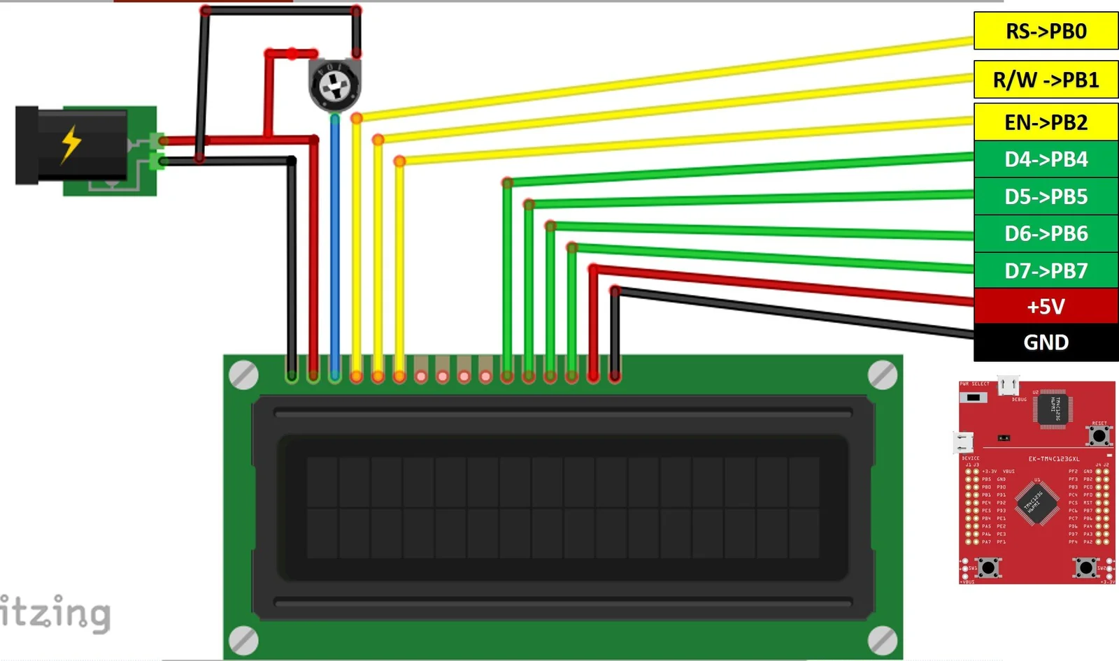
The figure above shows the complete wiring diagram for connecting the 16Ã2 LCD module to the TM4C123 microcontroller using 4-bit mode. The connections are:
- Power: VDD to VBus, VSS to Ground, V0 to contrast potentiometer
- Control: RS to PB0, E to PB2, RW to Ground (write-only)
- Data: D4-D7 to PB4-PB7 respectively
- Backlight: A to VBus, K to Ground
The contrast potentiometer (typically 10kÎĐ) allows adjustment of the display visibility - rotating it changes the voltage on V0 pin between 0V and VDD.
The following code demonstrates a complete LCD driver in 4-bit mode with initialization, command/data transmission, and text display functions.
#ifndef LCD_H
#define LCD_H
#include "TM4C123.h"
// LCD pin definitions (connected to PORTB)
#define RS (1 << 0) // PB0
#define EN (1 << 2) // PB2
#define DATA_MASK 0xF0 // PB4-PB7
// Function prototypes
void LCD_Init(void);
void LCD_Command(unsigned char cmd);
void LCD_Data(unsigned char data);
void LCD_Clear(void);
void LCD_SetCursor(unsigned char row, unsigned char col);
void LCD_Print(char *str);
void delay_us(int us);
void delay_ms(int ms);
#endif#include "lcd.h"
#define CYCLES_PER_US (SystemCoreClock / 1000000u)
//====================[ SysTick Delay Functions ]====================
void SysTick_Init(void)
{
SysTick->CTRL = 0;
SysTick->LOAD = CYCLES_PER_US - 1; // 1us delay at 50MHz
SysTick->VAL = 0;
SysTick->CTRL = 0x5; // Enable with system clock
}
void delay_us(int us)
{
SysTick->LOAD = (CYCLES_PER_US * us) - 1;
SysTick->VAL = 0;
SysTick->CTRL = 0x5; // Enable with system clock
while ((SysTick->CTRL & 0x10000) == 0);
SysTick->CTRL = 0;
}
void delay_ms(int ms)
{
while (ms--)
delay_us(1000);
}
//====================[ LCD Helper Functions ]====================
void LCD_EnablePulse(void)
{
delay_us(1);
GPIOB->DATA |= EN;
delay_us(1);
GPIOB->DATA &= ~EN;
delay_us(1);
}
void LCD_SendNibble(unsigned char nibble)
{
// Send nibble to PB4-PB7
GPIOB->DATA = (GPIOB->DATA & ~DATA_MASK) | ((nibble << 4) & DATA_MASK);
LCD_EnablePulse();
}
//====================[ LCD Initialization ]====================
void LCD_Init(void)
{
// Enable clock to PORTB
SYSCTL->RCGCGPIO |= (1 << 1);
while ((SYSCTL->PRGPIO & (1 << 1)) == 0)
;
// Configure PB0 (RS), PB1 (EN), PB4-PB7 (data) as output
GPIOB->DIR |= RS | EN | DATA_MASK;
GPIOB->DEN |= RS | EN | DATA_MASK;
GPIOB->DATA &= ~(RS | EN | DATA_MASK); // Clear all
SysTick_Init();
delay_ms(50); // Wait for LCD to power up
// Initialization sequence (8-bit interface mode to start)
LCD_SendNibble(0x03);
delay_ms(5);
LCD_SendNibble(0x03);
delay_us(150);
LCD_SendNibble(0x03);
delay_us(150);
LCD_SendNibble(0x02); // Set 4-bit mode
delay_us(150);
// Now in 4-bit mode: use full commands
LCD_Command(0x28); // Function set: 4-bit, 2 lines, 5x8 dots
LCD_Command(0x0C); // Display ON, Cursor OFF
LCD_Command(0x06); // Entry mode: increment cursor
LCD_Command(0x01); // Clear display
delay_ms(2);
}
//====================[ LCD Command/Data API ]====================
void LCD_Command(unsigned char command)
{
GPIOB->DATA &= ~RS; // RS = 0 for command
delay_us(1);
LCD_SendNibble(command >> 4); // Upper nibble
LCD_SendNibble(command & 0x0F); // Lower nibble
delay_ms(2);
}
void LCD_Data(unsigned char data)
{
GPIOB->DATA |= RS; // RS = 1 for data
delay_us(1);
LCD_SendNibble(data >> 4);
LCD_SendNibble(data & 0x0F);
delay_ms(1);
}
void LCD_Clear(void)
{
LCD_Command(0x01);
delay_ms(2);
}
void LCD_SetCursor(unsigned char row, unsigned char col)
{
unsigned char address = (row == 0) ? 0x80 + col : 0xC0 + col;
LCD_Command(address);
delay_ms(1);
}
void LCD_Print(char *str)
{
while (*str)
{
LCD_Data(*str++);
}
}
#include "TM4C123.h"
#include "lcd.h"
int main(void)
{
LCD_Init();
LCD_Clear(); // Ensure display is clear
LCD_SetCursor(0,0); // Set cursor to beginning
LCD_Print("ENCS4110 Lab");
while(1)
{
}
}Code Explanation â
Initialization Sequence
The LCD_Init() function implements the complete 4-bit initialization:
- Enables GPIO PORTB clock and configures pins as outputs
- Waits 50 ms for LCD power-on stabilization
- Sends
0x03(upper nibble) three times with delays (8-bit mode reset) - Sends
0x02(upper nibble) to switch to 4-bit mode - Sends configuration commands:
0x28(4-bit, 2 lines),0x0C(display on),0x06(entry mode),0x01(clear)
Nibble Transmission
The LCD_SendNibble() function:
- Masks out current data bits (PB4-PB7)
- Places the 4-bit nibble on PB4-PB7 (shifted left by 4)
- Generates enable pulse: delay â E high â delay â E low â delay
Command vs. Data
LCD_Command(): Sets RS=0, sends upper nibble, sends lower nibbleLCD_Data(): Sets RS=1, sends upper nibble, sends lower nibble
Cursor Positioning
The LCD_SetCursor(row, col) function calculates the DDRAM address:
address = (row == 0) ? 0x80 + col : 0xC0 + col;Then sends the address as a command.
String Printing
The LCD_Print(str) function iterates through the string and sends each character using LCD_Data().
Tasks â
Task 1: Display Your Name and ID â
Update the main program to display your name on the first line and your student ID on the second line of the LCD.
Requirements:
- Clear the display
- Set cursor to line 1, column 0
- Print your name (up to 16 characters)
- Set cursor to line 2, column 0
- Print your student ID
Hint:
LCD_Clear();
LCD_SetCursor(0, 0); // Line 1
LCD_Print("Your Name");
LCD_SetCursor(1, 0); // Line 2
LCD_Print("ID: 1234567");Task 2: Button-Controlled Name Scrolling â
Write a program that displays your name on the LCD and allows the user to scroll the text left or right using the two on-board push buttons (SW1 and SW2).
Requirements:
- Display your name on line 1
- Configure SW1 (PF4) and SW2 (PF0) with GPIO interrupts (falling edge, internal pull-up)
- When SW1 is pressed: Shift display left (command
0x18) - When SW2 is pressed: Shift display right (command
0x1C) - The display should not scroll automatically; only respond to button presses
Task 3: Bidirectional Continuous Scrolling â
Write a program that displays your name on line 1 and your student ID on line 2, with continuous scrolling in opposite directions after a button press.
Requirements:
- Display your name on line 1 and ID on line 2
- Initially, the display is static (no scrolling)
- When SW1 is pressed, start continuous scrolling:
- Line 1 scrolls right
- Line 2 scrolls left
- Pressing SW1 again stops the scrolling
- Use a timer interrupt to handle the scrolling at a fixed interval (e.g., every 500 ms)